PF-60 Laser Profilometer & Roughness Tester
Automatic Micro-Scanning System
Point Autofocus Probe (ISO 25178-605) – 3D laser spot for surface metrology, profilometry and roughness measurement, with 1 nm Z-axis accuracy.
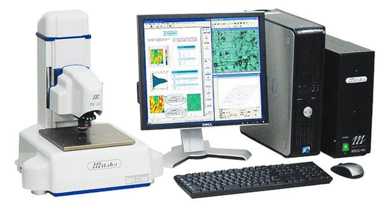
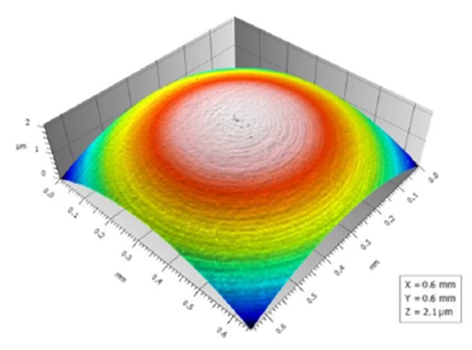
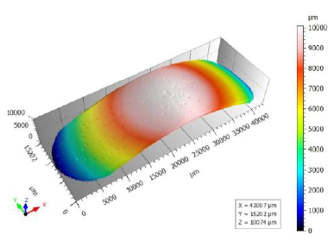
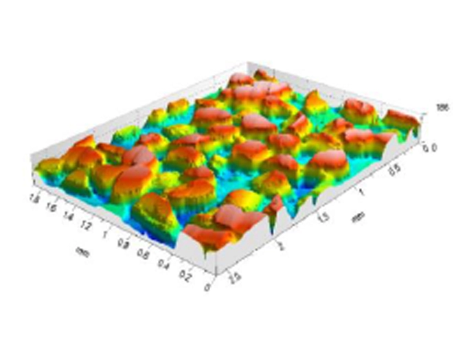
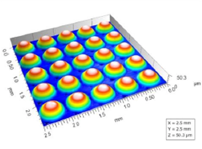
High-precision laser profilometer with 1 nm resolution over a 60 × 60 × 10 mm scanning area.
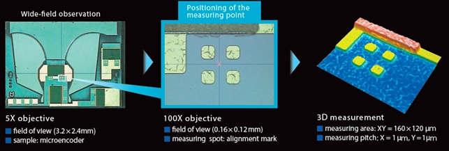
The PF-60 Laser Profilometer enables the measurement of opaque, reflective and transparent surfaces. Its 0.5 μm laser spot probe, combined with high-precision motorized XY positioning axes, allows real-time 3D profile measurement across areas spanning several tens of millimeters, with sub-micrometer resolution.
The Mitaka laser profilometer eliminates optical collimation errors between focal planes, mechanical alignment errors and errors caused by variations in the reflectivity of the samples under examination.
Standard system scanning area: X, Y, Z axes = 60 × 60 × 10 mm
Resolution: XY = 0.1 μm; Z = 0.01 μm
Exclusive Features of the Mitaka PF-60 Profilometer
- 3D laser measurement spot with a diameter of 0.5 µm
- 3D measurements with nanometric resolution (Z-axis = 1 nm)
- High-speed roughness and profile measurements (128,000 points in 6 minutes)
- Scanning of thin films and surfaces with high reflectivity or high light absorption
- Scanning and roughness/form measurement of transparent lenses and films
- Topographic mapping (surface textures) of large areas without stitching
- Reverse engineering (STL files) for FEM analysis and CAD comparison
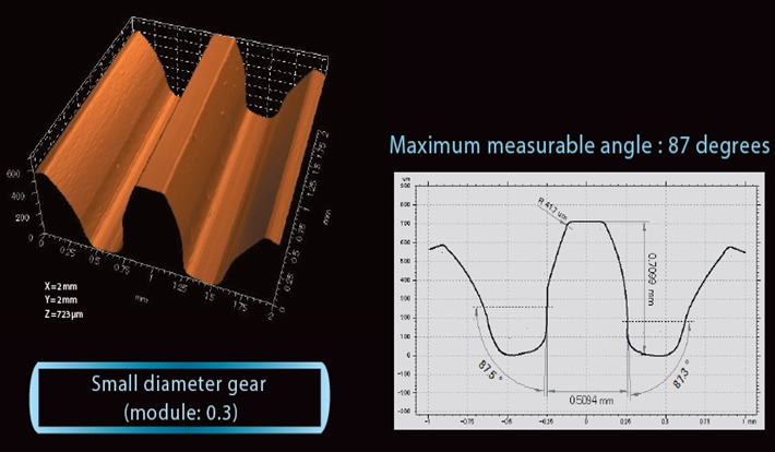
- Measurement of steep-angle profiles
With just a few simple operations, the Mitaka profilometer enables automatic scanning of large areas of samples of all types, including opaque, semi-reflective, transparent and highly reflective surfaces.
It delivers high-precision 3D measurements (1 nm), rapid reconstruction of surface topography and reverse engineering capabilities, with scan data export to CSV/STL files for FEM analysis, CAD measurements and comparisons, and prototyping.
Mitaka Laser Profilometer: No Stitching
Image stitching is a method commonly used by manufacturers of optical microscopes, confocal microscopes and non-contact profilometers to create a panoramic or high-resolution image by combining n individual fields of view.
This software-based process involves not only very long acquisition times, but also alignment issues, perspective distortions, geometric deformation caused by lens aberrations at the edges, and loss of resolution when assembling the resulting image. To achieve a seamless image, the individual sections must be acquired with precisely matching overlapping areas and identical exposure settings.
Images acquired by the PF-60 profilometer are not composites of square or rectangular fragments that must be aligned and merged at their edges. Instead, they consist of contiguous lines made up of individual points acquired using a laser spot with a diameter of 0.5 µm.
Profilometry Without Focus Variation
In conventional optical systems, surface topography reconstruction is achieved through software using the focus variation method. N images are acquired at different focal planes by moving the sample relative to the objective lens. For each image, the focal plane providing the best contrast relative to adjacent planes is identified using image analysis algorithms. The corresponding focal position (Z) is recorded by an encoder to calculate the surface depth.
This method presents several optical, mechanical and illumination-related challenges. The selected focal plane refers to the entire area viewed by the objective lens. Consequently, errors caused by distortion, exposure variations, vignetting and chromatic aberration can affect measurement accuracy.
Furthermore, when different focal planes are present within the same field of view, the resulting measurement represents a weighted average of heights, leading to reduced resolution when capturing small surface variations.
If the sample contains areas with different reflectivity, the software may incorrectly interpret highly reflective peaks as being closer to the objective. Moreover, this method cannot reliably examine highly reflective surfaces, such as wafers, glass and mirrors.
These uncertainties are compounded by additional random errors associated with the accuracy and repeatability of the mechanical movement and positioning of the sample or objective lens.
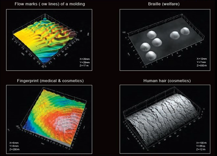
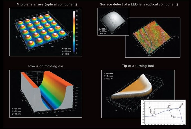
Lorem ipsum dolor sit amet, consectetur adipiscing elit. Ut elit tellus, luctus nec ullamcorper mattis, pulvinar dapibus leo.
Excellent Sharp-Edge Angle Detection Capabilities
The high-sensitivity autofocus sensor detects low levels of light reflected from the sample surface, enabling direct measurement of heights and sharp-edge angles.
Live Measurement
The device switches between objectives using a mechanical slider, allowing rapid changes from minimum to maximum magnification with a single manual operation. Operating parameters, live images and measurement results are displayed on the monitor in real time as measurements are performed.
Multiple work presets can be created to automate repetitive operations on batches of identical samples.
At the end of each measurement, a report containing the results of all tests performed is automatically displayed on the monitor and can also be printed. This applies to both manual and automatic measurement modes.
Approved by the International Organization for Standardization (ISO) as a non-contact measurement method. This technology is included in ISO 25178-6:2010 – Geometrical Product Specifications (GPS) – Surface Texture: Areal – Part 6: Classification of Methods for Measuring Surface Texture, under the designation “Point Autofocus Profiling” (ISO 25178-605: Autofocus Probe).
Measurement Principle and General Characteristics
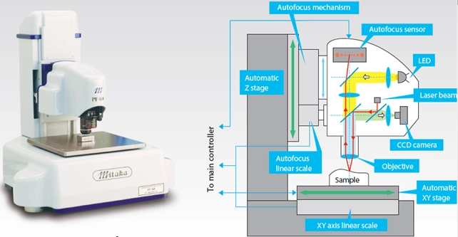
The PF-60 Profilometer consists of a laser autofocus (AF) microscope and a high-precision XY scanning stage. The AF system measures height along the Z-axis, while the XY stage moves the sample to acquire XYZ coordinate data for 2D and 3D measurements.
The PC-based control unit drives the PF-60 scanning stage according to the XY coordinates, enabling measurements across the entire travel range of 60 × 60 mm.
There is no need for data stitching, as the PF-60 is not subject to conventional measurement limitations, such as a restricted field of view. This enables high-precision measurements across large surface areas.
Point Autofocus Probe
The laser beam integrated into the AF microscope passes through the objective lens (indicated by the red line in the figure) and forms a laser spot on the sample surface, acting as a probe with a diameter of 0.5 µm.
The laser beam reflected from the sample surface passes back through the objective lens and forms an image on the autofocus sensor (AF sensor). The AF sensor detects the displacement of the laser spot in real time and adjusts the AF microscope to restore the focused position, where the laser spot is centered on the AF sensor.
The autofocus optical system filters out unwanted stray light and reflections to ensure accurate focusing.
Surface Texture Acquisition and Measurement Functions
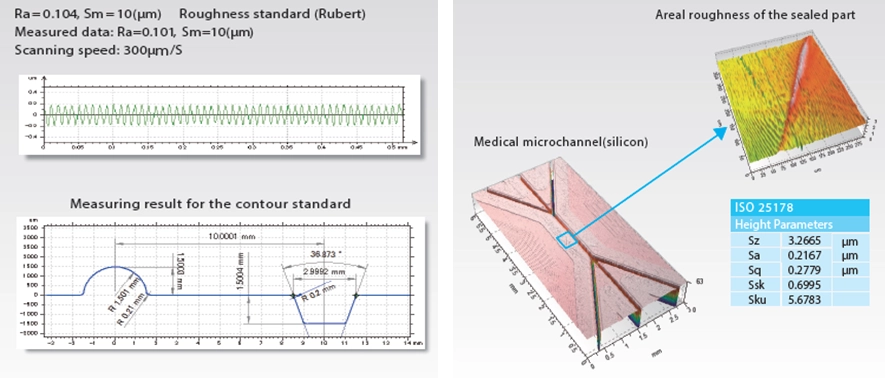
Roughness and Profile Measurements